[ main | F.A.Q | news | features | pictures | downloads | build your own ]
![]()
[ main | F.A.Q | news | features | pictures
| downloads | build your own ]
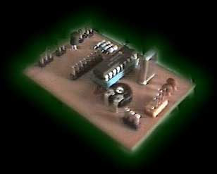
The uC board
OK, this is the most difficult part of the project... This is where your electronics skills are needed. The board is not very complicated but you need to etch/drill the board (veroboard or wirewrap could be used), solder the components and program the PIC. Head over to the download area and get the layout and component placement drawings. The component values are on the component drawing! The decoupling cap should be about 100nF I think, but it shouldn't be very critical. The load caps for the crystal aren't critical either. The connectors around the edges of the board could just be drilled holes, but it looks better and is a lot easier to connect cables if you use something like the connectors on the picture. Exactly what to connect to these is described in great detail in the section about connecting things... (surprise!). It's probably a good idea to put the PIC in a socket so you can remove it to update it's software! You need to program the PIC with the latest version of the code from the download section. The file you can download here is a MPASM assembler source file, you need to assemble it to a HEX file with MPASM and then program the PIC with this. You need the programmer hardware (it's very easy to build one that you connect to your paralell or serial port) and some matching software. This is one possible design, search the web if you need more info...
Simple testing:
To find out if your PIC is working and your programmer is OK, edit ELMP.ASM and look near the top for instructions on a simple test mode in which the PIC will send non-stop ´101010101010101010....´ data at 9600bps. Simply connect the serial output of the uC board to a serial port on your PC (RX pin and GND). If you connect the PIC to TX (Transmit) on your PC you'll fry the driver on that pin on the PIC because RS-232 uses +/- 12 volt as signal levels and the PIC uses 0/5 volts (I've done this so I know!). Anyway, fire up any terminal emulator like Teraterm or Terminate and set the port to 9600N1, you should see lots of UUUUUUUUUUUUUUUUUU etc. on your screen. If you don't see anything check your cables and port settings and if that doesn't work bring out your oscilloscope (if you have one...). First of all, look for a 4MHz sine wave on one of the crystal connectors, and then look for a nice square wave on the serial output pin, that should be about 4800Hz (each cycle is two bits at 9600bps). Good luck...